
Selecting and arranging
Selecting shapes, finding them in the object list, aligning, mirroring, rotating, laying flat on a face and multiplying in patterns.
Selecting
A click on a shape selects it. With Shift you add more or take them away again. A click on empty space clears the selection, and so does Esc. Drag a frame on the empty workplane to select everything it touches; with Shift held, the frame adds what was not selected and takes away what was. And Ctrl+A selects all visible bodies.
What is in your way you hide (“Hide selected”, Ctrl+H). Hidden shapes stay in the design, they are just not visible and stay out of the export; the export window says beforehand how many there are. Ctrl+Shift+H brings them all back. What should stay put you lock with the padlock at the top of the settings or with Ctrl+L. Locked shapes can neither be moved nor deleted by accident.
The object list
With many parts it is easy to lose track in the view. The object list (“Show object list” or Ctrl+Shift+O) shows all shapes as a list.
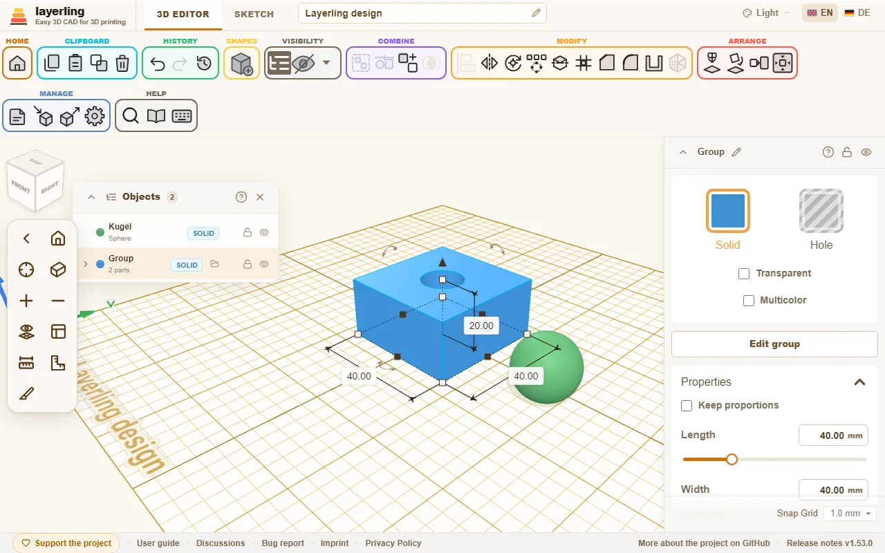
- A click on an entry selects the shape, including parts inside a group. With Shift held you add more entries or take them away again, just as in the view. The arrows fold groups open and shut.
- The label shows whether a part is “Solid” or “Hole”.
- Padlock and eye lock and hide single parts.
- “Rename” gives a part a name of its own; the pencil beside the name at the top of the settings does the same for the selected shape. Sensible names help enormously in larger designs.
- The search field finds shapes by name and by kind, so also "cylinder" or "hole". It also looks inside groups, however deeply nested: a group holding a match stays in the list and folds open to show the matching parts and the groups that lead to them. A group found by its own name shows all its parts when you open it.
- The arrow on the far left of the title bar folds the list down to its title bar and back.
The list sits docked just right of the view cube. Drag it by its title bar to put it anywhere on the workplane; it passes underneath the view cube and the camera bar. Drop it back beside the view cube, or double-click the title bar, and it docks again. Where it was and whether it was folded are remembered in this browser.
Typing a position
The card “Position” in the properties panel shows where the selected body stands, and you can type it: “X” and “Y” are the middle of its box on the plate, with the same signs as the distances shown on the workplane, and “Z (height)” is the height of its underside. X counts to the right, Y towards the back and Z up, by the right-hand rule as in Tinkercad and CAD programs; the axis arrows on the plate show the directions. The values go in the unit you set, and the sliders reach as far as dragging does.
Parking parts beside the plate
You can drag a shape past the edge of the plate and leave it there, about one plate width beyond each side, to keep it for later. The arrow keys move it as far as you like. A parked part still belongs to the design and goes into the export with everything else. To leave it out, hide it or export only the selection. If you have picked a printer, layerling warns at export when something sits outside its plate.
Snapping while moving
When you drag a shape across the workplane, it snaps to other shapes: its left, right, front or back edge or its centre lands exactly on an edge or centre of another shape. A pink guide line shows what it is holding on to. That way two parts sit flush side by side or centred one behind the other without typing numbers. It works with the grid switched off, too.
Hold Shift while dragging to keep the move on one axis: the shape follows whichever direction, X or Y, you have dragged further in, and leaves the other alone. Best press Shift once you are already dragging; on a shape that is not selected yet, a click with Shift only adds it to the selection.
With Alt already held when the drag begins, you drag a copy, as in Tinkercad: the shape stays where it is and the copy lands where you let go. Pressing Alt only on the way pauses snapping; the shape then follows the grid only. A copy, too, snaps only once you let go of Alt on the way. To switch snapping off for good, use the grid menu in the bottom right (“Snap to shapes”) or the settings. For now only moving on the normal workplane snaps, not lifting and not resizing.
Aligning
Two or more selected shapes are lined up with “Align”: points appear around the selection for left, centre and right, front, centre and back, and top, centre and bottom. A click on a point moves all shapes there. If you first click one of the selected shapes, it stays in place and the others line up with it.
A shape turned at an angle, say by 45°, has its box round it to line up with, not its own edges. To line up with the edges, set a workplane on a face of that shape first (“Place workplane”, then click the face): the points then stand on the axes of that plane, and the shapes are measured and moved along them, as in Tinkercad. Reset the workplane to line up along the plate again.
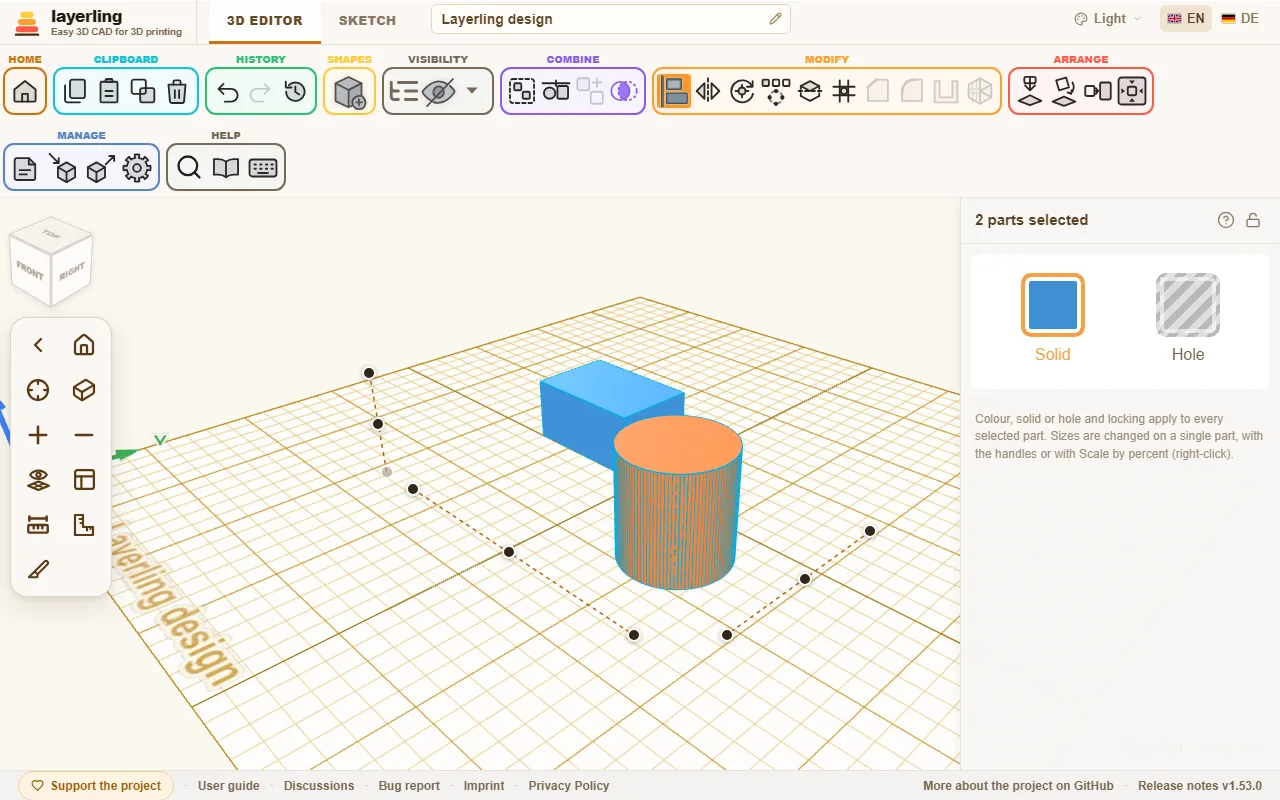
The key is L. Esc cancels.
Mirroring
“Mirror” (M, or right-click the selection and choose it) flips the selection across a plane: “left-right”, “front-back” or “top-bottom”. Click the matching axis arrow. That is handy for symmetric parts: build one half, copy it and mirror the copy.
Rotating and setting the pivot
You rotate with the curved arrows on the shape, with the numbers in the settings or with R in 45° steps. When you drag on the rotation circle, the turn snaps to every tick, that is every 22.5°; hold Shift for finer steps, and extra ticks appear every 11.25°. Drag outside the circle to turn freely in 1° steps, or in 45° steps with Shift. Normally the selection turns about its centre. Sometimes it should not, for example when a tilted tube is to be turned further at its end. For that there is “Set rotation pivot”: afterwards click on a face. A flat face supplies its centre, for example the axis of a tube end. The selection now turns about that point. A second click on the tool removes it again.
The angles stay with the body. In its settings, “Rotation” shows them as “About X”, “About Y” and “About Z (height)”, named like the position: Y runs across the plate, Z is up. Type an angle there and the body turns to it - about its centre, or about its own pivot if it has one. While a turned body is selected, its angles also show below it on the workplane; “Show the angles of turned bodies” in the settings switches that off.
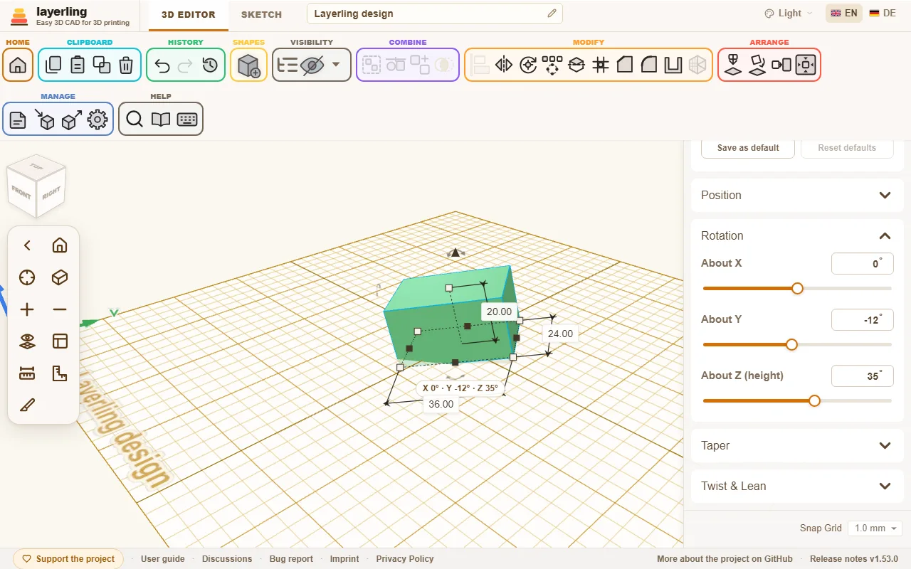
With one body selected, the pivot belongs to that body: select other parts and come back, and it is still there. It moves, turns and scales with the body, is saved in the project and comes back with Undo. Under “Position” the pivot has its own X, Y and Z, which you can type or nudge, and “Remove” takes it away. You can also drag the pivot's red marker with the mouse: it slides over the surface of the bodies and snaps to corners, edge midpoints and edges, so a hinge pin lands exactly on a corner. With several bodies selected the pivot is only for that selection, and a new selection removes it.
Laying flat on a face
Should a part lie on its best side for printing? Select it, click “Lay flat on face” and then the face that should go down. While you move the pointer over the part, the face under it lights up, so you see which one you are about to pick; turn the view to check the other sides. The part turns so that this face rests on the workplane.
Two parts should meet face to face, or line up flush? Select the part that should move, click “Align faces”, then click its face and after that the face of the other part. In the panel, “Face to face” puts the faces against each other (back to back, touching), “Flush” lays them in one plane side by side; “Gap” leaves room between them, for example for clearance. “Align” moves the part: it turns the shortest way until the faces are parallel - not at all if they already are - and then slides only towards the other face, so it keeps its place sideways. The other part stays where it is, and one Undo takes it all back.
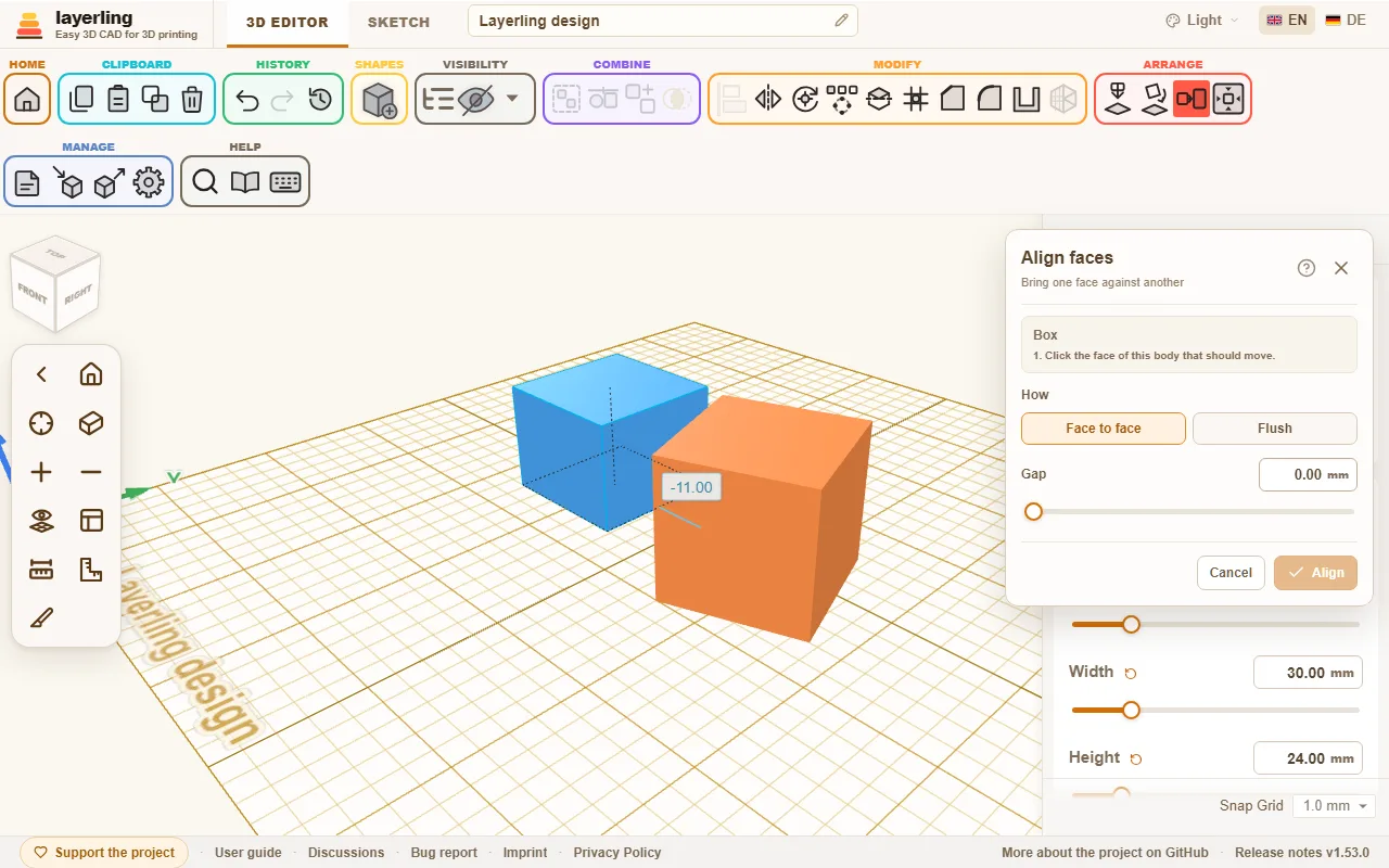
Just as simple are “Drop to workplane” (D), which drops the selection onto the workplane, and “Center on workplane”.
C picks the selection up, like Cruise in Tinkercad: it follows the mouse pointer and lies down on the face of another body you are over, sloped ones too. A click sets it down there, Esc leaves it where it was. Its underside then rests on the face, lined up with the face's edges as a new shape would be; it keeps its own turn about its up axis. Several parts travel together and keep their spacing. Over the empty plate, C stands a tilted part upright on the workplane again.
Patterns: row and circle
For hole grids, bolt circles and rings of teeth there is the “Pattern”. Select the shapes to be multiplied and click it in the ribbon.
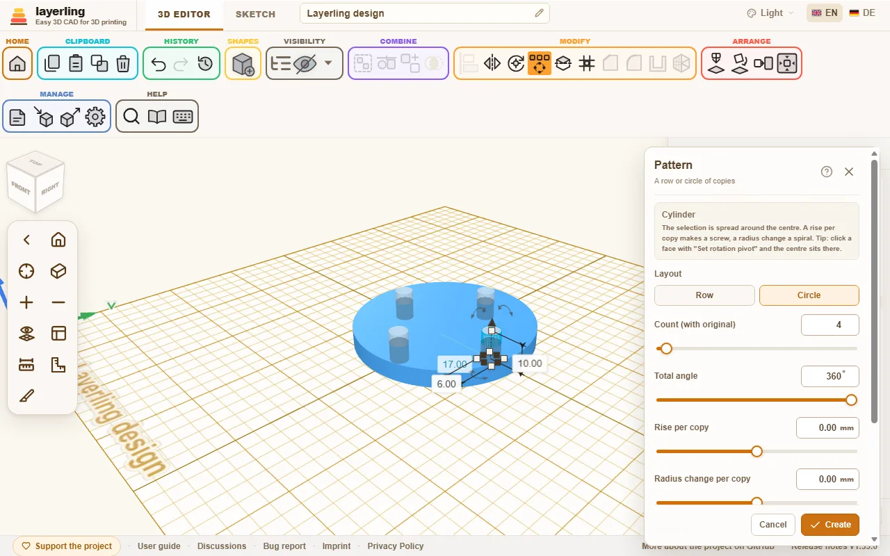
- “Row”: The selection is repeated at equal distances. The row steps along all three axes at once, with “Spacing X”, “Spacing Y” and “Spacing Z (height)”: one of them gives a straight row, two or three a diagonal row or a staircase. A negative spacing lays the row the other way.
- “Circle”: The selection is spread around a centre. How many copies there are you set under “Count (with original)”, and the “Total angle” is 360° for a full circle. Choose whether the copies turn along. “Rise per copy” lifts every copy a little more than the one before (a screw or an ascending spiral), and “Radius change per copy” moves it further from the centre or closer to it (a flat spiral); together they give a conical spiral.
Tip: first set the pivot on a face with “Set rotation pivot”, then the centre of the circle lies exactly there.
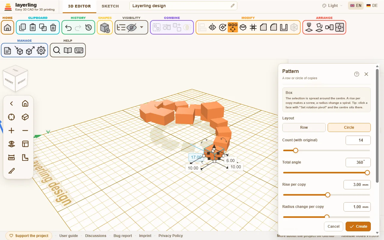
The copies first appear as a preview. Only “Create” creates them. If the copies are holes, group them afterwards with the body they should cut into.
Hole pattern on a face
For vents, speaker grilles, baskets and enclosures the “Hole pattern” spreads holes evenly over a flat face. You no longer have to make one hole, repeat it and set it onto the wall. Select exactly one body and click “Hole pattern” in the “Modify” group of the toolbar, next to the pattern. You can also right-click the body, or find it with Ctrl+K.
- Click a flat face of the body. The whole flat face around your click counts, not just the triangle under the pointer. A curved face does not work: you get a hint and click a flat one instead.
- In the window, set how the holes look and lie:
- “Hole shape”: “Round”, “Square”, “Rectangle”, “Hexagon” or “Slot”.
- Size: the “Diameter (Ø)” of a round hole, the “Side length” of a square one, “Width” and “Height” for a rectangle and a slot. For the hexagon the size is the “Diameter across the corners (Ø)”.
- “Spacing centre to centre”: the distance from one hole's middle to the next. If it is smaller than the holes allow, layerling raises it to the smallest possible value so a wall stays between the holes.
- “Wall between the holes”: the same distance said another way: the wall left between two neighbouring holes, which is the wall thickness in the print. Set it and the spacing centre to centre follows, and the other way round. For hexagons, rectangles and slots layerling measures the least distance between their edges.
- “Arrangement”: “Grid” puts the holes in rows and columns. “Staggered” shifts every second row by half a spacing and moves the rows closer, so every hole has neighbours at the same distance - with hexagons that makes a honeycomb.
- “Margin to the face's edge”: the clear distance between the holes and the edge of the face. Only holes that lie wholly inside the face minus this margin are made; anything that would reach beyond it is left out. The margin also holds around openings in the face.
- “Depth”: “Through the whole body” (the default) cuts through the whole wall. With “Custom depth” you give the depth in millimetres, for recesses, say.
- The holes show at once as a preview on the face and follow every value. The window says how many holes fit. “Another face” chooses another face, Esc closes the tool, and like the other tool windows it moves by its title bar.
- Only “Create” makes the holes.
The holes are ordinary holes grouped with the body, just as after “Group”: nothing is baked in. “Ungroup” dissolves the group again and frees every hole, which you can then move, change or delete one by one. The whole thing is one step for “Undo”. The tool does not make more than 400 holes at once; make the holes bigger or the spacing wider then.
An AI can do the same through the MCP bridge with layerling_perforate_face (see the chapter AI with MCP).
Changing several parts at once
With several parts selected, the properties panel on the right shows how many there are and offers what applies to all of them together: “Solid” or “Hole”, one colour for all (a click on “Solid” opens the colours) and the lock. With a mixed selection, one click makes them all solids or all holes. Locked parts stay as they are. Sizes are changed with the handles, with “Scale by percent” or by typing a number into a size label. With several parts the number is the size of the whole selection: every part grows with it, the spaces between them too, as when you drag a handle. Solid and hole also work with a right-click or the S and H keys.
Scaling by percent
To make one or several parts larger or smaller by the same share, say all the parts of a print file by 20 %, use “Scale by percent”. Select the parts, right-click them and choose “Scale by percent”, or search for it with Ctrl+K.
Under “New size” you type the new size as a percentage of the current one: 120 % is a fifth larger, 50 % half the size. Width, depth and height change alike, so the proportions stay. The bottom stays where it is, so nothing sinks into the plate.
With several parts you choose how they grow:
- “Together”: The parts grow around their common centre, and the gaps grow with them. The whole becomes larger as if it were one part.
- “Each in place”: Every part grows where it stands, and the gaps between them stay the same.
Only “Scale” changes the design, and one step back undoes it. Locked parts stay as they are.
Undoing
“Undo” (Ctrl+Z) and “Redo” (Ctrl+Shift+Z or Ctrl+Y) step through your history. How many steps travel with the saved design you set in the settings under “History”.
Looking back: the history view
“History”, next to undo and redo, opens a view of your history without changing anything. The work area shows the design as it was, and a slider at the bottom runs through every undo step: all the way to the right is the current state, each step to the left is one undo earlier, and states you have undone sit to the right of the current one. The arrow keys step through the states, Esc returns to the current state. You can turn and zoom the view meanwhile, but nothing can be selected or moved; the design itself stays exactly as it is. If the bar covers something, drag it away by its title bar; a double-click on it brings it back.
Two things you can take along from an earlier state. “New project from this state” puts that state into a new design in the overview, named after this one with the time of that state in brackets - a design saved before layerling recorded times says "copy" instead - and with the history up to that point, so undo keeps working there. “Export this state” opens the usual export with that state as the design, so you can save it as STL, 3MF, STEP, a picture or a LYL file with the history up to that state.
“Delete history” sits alone at the bottom left of the bar. After a question it removes every earlier step for good: the design keeps the state it has now (not the one shown), Undo has nothing to go back to and a file saved afterwards carries no history. Use it to share a design without its past, or to start the undo steps over. It cannot be undone; to share a file without touching your own design, choose “None” when exporting instead.